|
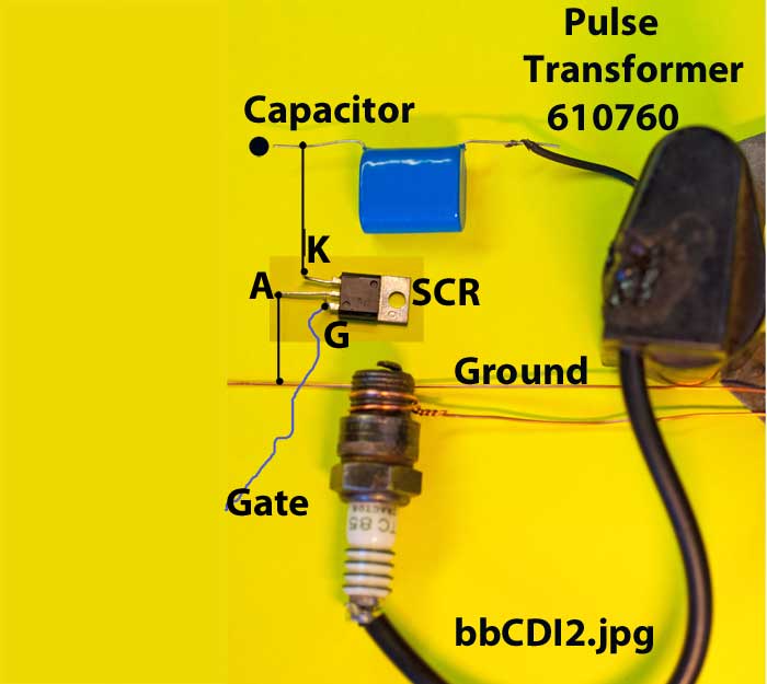
Now if we add an electronic switch, Silicone
Controlled Rectifier, SCR between the capacitor lead and ground, it could be used to fire the spark when a little trigger
pulse ( like ½ Volt) is applied to the gate. In its normal state, the SCR is like an open switch, like it is not there, but
when triggered by the gate, it turns in to a closed switch instantly, until the voltage decays to zero and then the SCR returns
to the open state. This trigger pulse comes from a trigger coil and occurs over a very small, precise angle of crank shaft
rotation. There are usually a resistor or two and a little capacitor in the gate circuit for signal conditioning.
|
| Figure A-3 |
In
Figure A 3, bbCD3I.jpg, we need at least one coil on a Stator and a magnet on the flywheel to generate one or more pulses
to be used as an input to charge the capacitor. I call these the Ignition Charge Coil, ICC. The ICC has many many more turns
of wire than other coils on the stator because it needs to generate the much higher voltage. The wire is a small gauge since
the average current is low. The resulting voltage has both positive and negative components and thus resembles an Alternating
Current, AC.
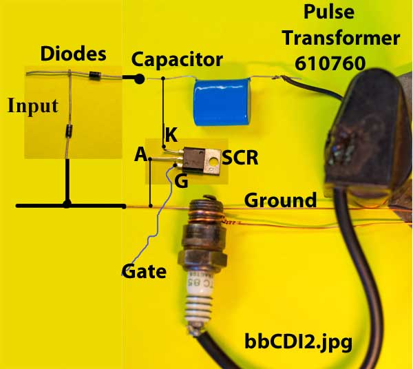
If
we add a diode to the circuit, this passes only the positive (or negative) pulses to charge the capacitor. There is a second
diode in the circuit which sets up a current in the charge coil during the unused pulses which, when reversed by the magnets
makes for a higher output voltage.
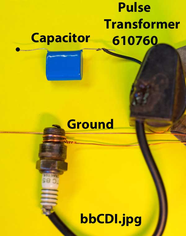
When
the SCR fires, it dumps all the energy stored in the capacitor directly into the primary of the Pulse Transformer and fires
the spark. At every opportunity, I remind all to always have a grounded spark plug connected to the Pulse Transformer when
turning the flywheel to place a limit on the very high voltage produced.
|
| Figure A-4 |
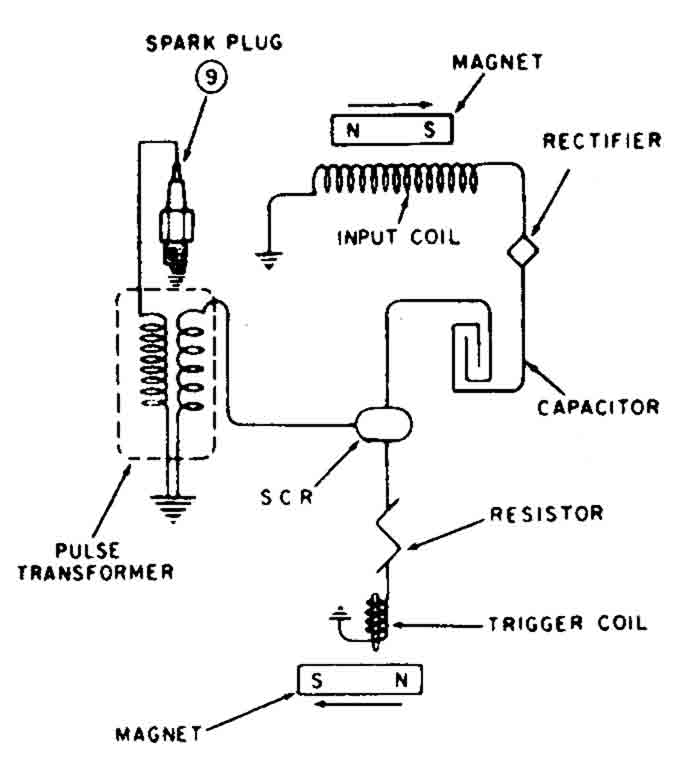
Figure A 4, techscma.jpg is the circuit
diagram of the TECUMSEH Solid State Ignition in all the manuals. I have a real problem with this circuit diagram. If one follows
the path for the current to charge the capacitor, it is open at the electronic switch or Silicon Controlled Rectifier, SCR.
Thus this circuit will never work.
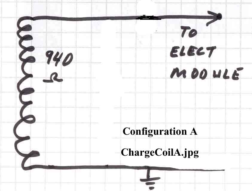
The ICC for the 610759 comes in two different
internal configurations. Configuration A has the charging diodes D1 and D2 physically located on the Printed Circuit Board,
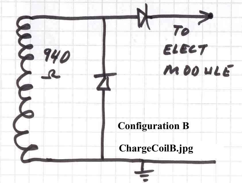
PCB in the Electronics Module and Configuration B has the diodes located in the ICC. Configuration B does hot use a PCB. All
the ESKA single cylinder ignitions I have seen follow Configuration A except for having only one trigger coil. The circuit
diagrams of the Charge Coil for the two configurations are shown below in Figure A 5, ChargeCiolA.jpg and Figure A6, ChargeCiolB.jpg
|
| Figure A-5 |
|
| Figure A-6 |
It is easy to tell the difference between the
Configurations by looking at the two wires coming out of the ICC. For the Configuration A ICC with out the diodes, the wires
are both BLACK , as a clue to being AC. For the Configuration B Ignition Charge coil with the diodes, the wires are one BLACK
and the other RED, as a clue to being DC. The BLACK one is grounded and the RED one feed the Electronics module. Before I
learned of the different configurations,
I checked the resistance of a ICC and found it open. It turned out to be a Configuration B with a diode in it. One can measure
the resistance in both directions by reversing the red and black meter leads. If the meter reads between 925 and 960 ohms
in both directions, then the configuration is A, no diodes in the Charge Coil. If you have a diode test function, and measure
it, you should get zero volts in both directions for Configuration A. The diode test will yield a .9 Volt reading if the two
diodes are present as in Configuration B.
I assume that the ESKA is the same as Configuration
A, but need to test it the next time I have one to repair. If the ICC failed, it would go open.
Schematics 610759 and ESKA Single Updated from 29 Oct 05
|
| Figure A-7 |
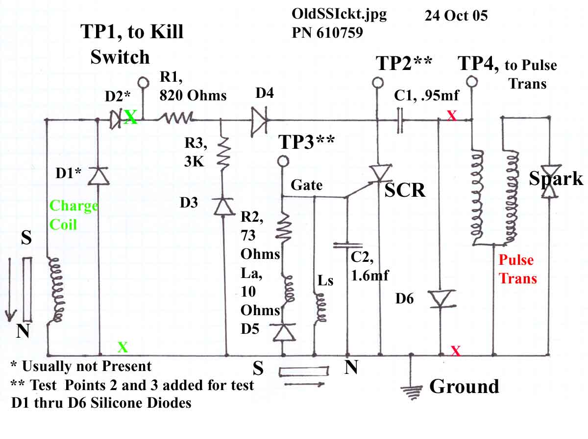
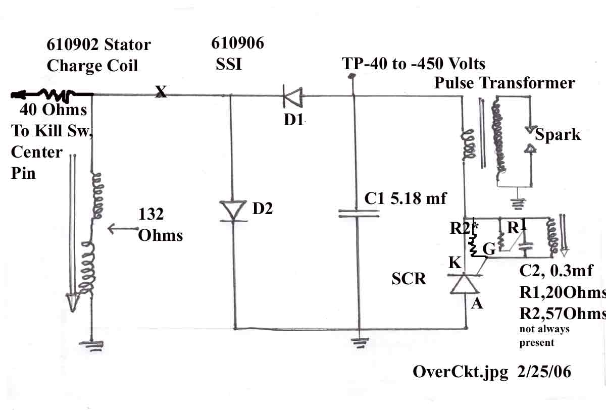
Figure A 7, oldssickt.jpg, showers the schematic
for the 610759. The parts between the RED and the GREEN Xs are the Electronics Module. The parts to the right of the RED Xs
are the Pulse Transformer. The parts to the left of the GREEN Xs are the ICC Configuration B. For Configuration A, the GREEN
Xs would be moved to the left of the diodes D1 and D2.
You can follow the path for charging the main
capacitor, C1 from TP1 to TP2. These were test points I used to look a the wave forms of the voltages when running the SSI
on the engine simulator.
Near the RED Xs, you can see diode, D6. This
is the diode disconnected by the cut when repairing the unit and replaced with a new one at the Pulse Transformer for both
the ESKA and 610759. The ESKA outboard
would be the same as Configuration A, except there is only one trigger, Ls. The La, R2 and D5 would not be in the circuit.
L is the symbol for an inductor or trigger coil , the s is for start and the a for advance.
The wire for the Kill Switch is connected to
the output of the charge coil to short out this charging voltage to ground, thus no spark. In some configurations, the wire
is directly connected to the charge coil. In another configuration, there are diodes in the circuit. In yet another configuration,
there is a 40 ohm resistor in the circuit. Kohler uses a 220 Ohm resistor in series with the kill switch.
We
can follow some scope pictures of the Voltage wave forms thru the circuit.
Figure
A-8, Reserved
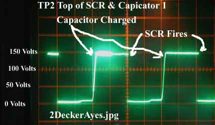
Figure A-9, 2DeckerAyes.jpg shows what the voltage looks
like after the Diodes and at the input to the main capacitor, C1.
|
| Figure A-9 |
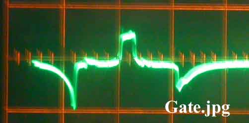
Figure A-10, Gate.jpg shows what it gate voltage looks
like for a 610759 which has two triggers, one for TDC starting and the other for the advanced spark. The short negative pulse
is for the Advance spark and comes first, followed by the stronger negative pulse. As the RPM increases, the pulses grow.
When the short pulse is strong enough, it takes over triggering the ignition.
|
| FigureA-10 |
Schematics
for Solid State Ignition PN 610906 :
|
| Figure A-12 |
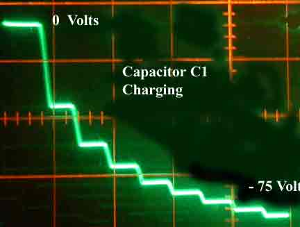
C2 in the trigger circuit turned out to be a
Thermister, not a capacitor. Figure A -12, C1charging.jpg shows the charging of the capacitor
for a 610906 with a 20 amp Stator. Here the voltage going to the SSI is negative and the capacitor charges in steps because
of there being two coils on the Stator and 18 magnetic poles on the flywheel. The output of the ICC looks like a continuous
sine wave instead of just a pulse every revolution as in the 610759A.
|
| Figure A-13 |
|