|
| Figure1-11 |
Ignition Coil
The Coil with associated connections
is shown in Figure 1- 11, Coil.jpg.
If the Ignition Coil does not have
an internal ballast resistor, an external ballast resistor will have to be added in series with the + lead.
Installation Options
Wire Conventions: To make it easier
for us to communicate clearly, the colors of wires is defined as follows:
Red /Orange ...........................Plus
12 Volts DC
Black
......................Minus 12 Volts DC and Ground
Yellow
.............................Timing / Trigger Pulse
Blue
...........................Negative side of Ignition Coil
Switch
ology
There is a great variety of key switches, but one looks
like this, Figure 1-12,MagSw.jpg

Details on key switches
can be found at http://www.kochsales.com/?page_id=29 . In the switch ology world, you may see other letters like:
A
- Accessories
I
- Ignition
R
- Run or Regulator or Rectifier
Installation Options Updated from December 11,
2009
Most
of the ignitions being replaced are old Capacitance Discharge Ignitions , CDI or Solid State Ignitions, SSI. These ignition
systems, like magnetos, get their electrical power from flywheel magnets rotating past a coil in the ignition system. To shut
the ignition off, this coil is connected to ground by the key ignition switch. This is most unsuitable for the replacement
ignition which gets its power from the battery and is turned on / off by connecting or disconnecting the battery power. The
three installation options below are ways around this fundamental problem.
Option
1 - Use existing key switch for a magneto or CDI ignitions
Option
2 - Adding a new Toggle Switch and Pilot Light
Option
3 - Adding a new Key Switch
Option
1 - Use existing key switch for a magneto or CDI ignitions
Option
1 uses the old key switch, but leaves the M or Magneto terminal not connected. We need power for the replacement ignition
both during Start and Run key switch positions. If we connected the Replacement Ignition to the L or A terminal, we would
have power in the Running mode, but usually not during the Starting mode. If we connected the Replacement Ignition to the
S terminal, we would have power in the Starting mode, but not during the Running mode. So we need to tap into both wires coming
from the switch, one for Starting mode and the other for Running mode. If we just spliced
these two connections together and ran the wire to the Replacement Ignition, we would have a new problem; the starter would
run all the time. To solve this problem, a diode is placed in series with the connection to the S terminal to block the current
that would flow from the Run connection. To keep Mr. Murphy form getting these two connections mixed up, a diode is placed
in both connections to the switch. Again, for Mr. Murphy, the wires going from the diodes to the switch are RED and the wires
going from the diodes to the replacement Ignition are ORANGE. To make the conversion to the Replacement Ignition as easy as
possible, a pre- wired Diode Wire Harness can be provided which already has the diodes, with the correct polarity, soldered
in it and wires labeled. The Diode Wire Harness is shown in Figure 1-13, Diodes.jpg.

|
| Figure 1-13 |

|
| Figure1-14 |
The replacement ignition draws about 3 Amps,
so I use 6 Amp diodes for reliability. Realizing that the starter solenoid will produce a voltage spike when the current is
removed, I picked a 600 Volt Peak Inverse Voltage, PIV which will be more than sufficient.
Figure 1-14, Option1.jpg Shows the wires to
be added for Option 1. The existing wires are not shown and should not be disturbed unless to tap into.
Mike Brooks, brokndwn64@gmail.com , Phone 585-243-7765,
offers a kit with all the components in Figure 1-14, Option1C.jpg except the pre-existing switch. The kit comes with the pre-fabricated
Diode Wire Harness with only one end of the wires made up so the wires can be trimmed to fit the installation.
Option 1 Installation Instructions:
1. Turn the key switch to off and disconnect
the negative battery cable.
2. Install the trigger coil making sure it is
centered over the tall trigger pin, set the air gap as marked on the trigger, about .015". This controls the RPM for the transition
to advanced spark. Tape up and stow the ICC connection to the stator.
3. Install the Ignition Coil in a cool place
and so the spark wire reaches the plug.
4. Install the Control Module in a convenient
but cool place. If installed on plastic, run a wire to ground the case.
5. Locate the wire that comes from the S terminal
on the key switch and tap the RED Diode Wire Harness wire marked " To Start" into it with . See Figure 1-15 TapSplice.jpg
. The other end of the wire goes to the solenoid , which might be easier to get to and should have a post for a ring terminal.

|
| Figure 1-15 |
6. Locate the wire that comes from the A, L or R terminal on the
key switch and tap the RED Diode Wire Harness wire marked " To Run" into it.
7. Connect the ORNGE Diode Wire Harness wire marked "Ignition Coil
+" to the Ignition Coil +.
8. Connect the ORANGE Diode Wire Harness wire marked " CM-C" to
the Control Module terminal C with a bullet connector.
9. Connect the YELLOW wire from the Trigger Coil to the Control
Module terminal B with a bullet connector.
10. Connect the negative terminal on the Ignition Coil to the Control
Module terminal D to with a bullet connector using BLUE wire.
11. Connect the spark plug wire to the Ignition Coil and uninstalled
spark plug. Wrap some bare wire around the threads of the spark plug and ground the other end.
12. Turn the key switch to off and reconnect the negative battery
terminal.
13. Turn the key switch on and look for a spark at the spark plug
when turning the switch on and off.
14. Spin the flywheel by hand and see if you get sparks.
15. Install the spark plug and blower housing and fire up the engine.
Option 2 - Adding a new Toggle Switch and Pilot Light
Another way the Automotive Replacement Ignition can get its electrical
power is directly from the battery by adding a fuse, toggle switch and pilot light, but this has the disadvantage that if
the engine ignition left on, it will eventually run down the battery. A LED pilot light is added here to help remind the operator
to turn off the ignition. This installation is ideal for welders and compressors that do not have the original key switch.
Figure 1-16,Option2.jpg , shows a mockup of Option 2.

|
| Figure 1-16 |
Most tractors have a heavy red wire that goes
from the + battery terminal to the always hot post of the starter solenoid (1). ( Following the numbers on the figure.) This
is a good place to pick up the needed power.(Always disconnect the battery ground before messing with the hot wires.) This
connects to a 5 Amp fuse (2) and on to a new toggle switch (3). The switched power (4) goes to three devices;
1. The + side of the Ignition Coil.
2. Terminal C on the Control Module
3. The pilot light
The terminals of the Control Module can be identified
by noting the transistor. The terminal closest to the transistor is A which is not used here since the ground for the Control
Module is provided by mounting it of the metal of the tractor.
The pilot light has a ground that can be easily
connected to a 5/16 ring terminal of the pilot light assembly. The yellow wire, 5, connects the trigger signal form the Trigger
Coil to terminal B of the Control Module. Last, the BLUE wire, 6 connects the switched output of the Control Module , terminal
D to the negative or - side of the Ignition Coil.
Mike Brooks, brokndwn64@gmail.com, Phone 585-243-7765 offers a kit with all the components in Figure 1-16 except
the battery, battery cable and solenoid. The kit comes with the pre-fabricated wire harness with only one end of the wires
made up so the wires can be trimmed to fit. The various crimp connector are provided.
Option 2 -Installation
Instructions
1 Disconnect the negative battery terminal.
2. Locate a desired
place on the dash board , drill a ½ hole for the new toggle switch and a 5/16 hole for the pilot light about 2 inches above
the switch hole. See Figure 2-17, Switch.jpg.

|
| Figure 1-17 |
3. Install the switch in the bottom hole and
the pilot light above it. The 5/16 ring terminal goes on the pilot light on the back side of the dash board and is for the
pilot light ground. The black wire from the pilot light to the 5/16 ring terminal then tighten to mounting nut. If the dash
board is plastic, connect the black pilot light wire to a suitable ground.
4. Connect the pilot light red wire to the short
red wire coming off the new toggle switch . When installing the Pilot Light, the wires have to be inserted in the 5/16 hole
first. Because they are soldered to the Pilot Light, they must be of a smaller gage to fit thru the hole and they need to
be spliced after installed. Splice them by t twisting them tightly together with a pliers. Then install a wire nut and tape
tightly with electrical tape.
5. Connect the red wire coming off the switch
with the ring terminal to the Ignition Coil +.
6. Connect the red wire coming off the switch
with the bullet connector to the Control Module terminal C .
7. Connect the wire coming off the switch that
has a 5 amp fuse in it to the always hot side of the solenoid using a 1/4 inch ring terminal.
8. Connect the YELLOW wire from the Trigger
Coil to terminal B on the Control module.
9. Connect the Control Module terminal D to
the negative terminal on the Ignition Coil with BLUE wire.
10. Check to make sure that the Pilot Light
and Control Module are grounded.
11. Connect the spark plug wire to the Ignition
Coil and uninstalled spark plug. Wrap some bare wire around the threads of the spark plug and ground one end.
12. Turn the new toggle switch to off and reconnect
the negative battery terminal.
13. Turn the toggle switch on and look for the
Pilot Light to light. You should get a spark at the spark plug when turning the switch on and off.
14. Spin the flywheel by hand and see if you
get sparks.
15. Install the spark plug and blower housing
and fire up the engine.
Installation Option
3 - Replacing the Key Switch
A third way to power the Automotive Replacement
Ignition is to get its electrical power from a new key switch made for battery powered ignitions. Figure 1-18, Option 3C,
repeated here, shows a mockup of Option 3.

|
| Figure 1-18 |
Here the white wire from key switch terminal
I provides power directly to both the Control Module terminal D and the + terminal of the Ignition Coil. There are too many
different types of switches being replaced for me to provide details on the other wires.
Option 3 Installation
Instructions
1. Disconnect the negative battery terminal.
2. Install the Trigger Coil, set the air gap
to as marked on the unit, typically .015". This air gap controls the RPM for the transition to advanced spark.
3. Install the Ignition Coil in a cool place
and so the spark wire reaches the plug.
4. Install the Control Module in a convenient
but cool place. If installed on plastic, run a wire to ground the case.
5.Remove the old key switch and note the terminal
markings on the back of the switch. Install the new key switch and note the terminal markings on the back of that also. Install
the new switch connector. On the white wire ( shown here) splice two red wires and route them one to the + terminal of the
Ignition Coil and terminal C of the Control Module. Splice the other wires following the markings on the back of the switch.
6. Connect the YELLOW Trigger wire to the Control
Module terminal B with a bullet connector.
7. Connect the negative terminal on the Ignition
Coil to the Control Module terminal D to with a bullet connector using BLUE wire.
8. Connect the spark plug wire to the Ignition
Coil and uninstalled spark plug. Wrap some bare wire around the threads of the spark plug and ground other end.
9. Turn the key switch to off and reconnect
the negative battery terminal.
10. Turn the new key switch to the RUN position
and look for a spark at the spark plug when turning the switch on and off.
11. Turn the new key switch to the START position
and look for a spark at the spark plug when turning the switch on and off.
12. Spin the flywheel by hand and see if you
get sparks.
13. Install the spark plug and blower housing
and fire up the engine.
Trouble Shooting Guide
for all three Options.
Connect a grounded spark plug to the ignition.
When power is applied and removed from the circuit, you should see a spark. This is a good over all check that the ignition
is set up right.
The spark timing is determined by the physical
location of the trigger pins on the flywheel. The transition from the TDC to Advanced spark as the engine increases in RPM
is controlled by the air gap between the trigger pins and the Trigger Coil. It is the nature of magnetic induction that the
trigger coil voltage increases with RPM. Increasing the air gap, reduces the trigger voltage causing the transition to be
delayed to a higher RPM. Decreasing the air gap increases the trigger voltage and causes the transition to occur earlier or
at a lower RPM.
With and with out a spark plug installed provides
two conditions of compression and hence two test RPMs. With an old spark plug installed for normal compression , an inductive
timing light will show the tall trigger pin just before the magnet when triggering the TDC spark. With no spark plug installed
for a no compression and a higher RPM, an inductive timing light might show the short trigger pin just before the magnet when
triggering the Advanced spark. If this test still shows the tall pin, the transition from the TDC, start spark to the advanced
spark has not occurred yet. Before you put the blower housing on you can run a cold engine for half a minute. If you try this,
you should see the spark advance as the engine begins to run.
Voltage measurements:
Be sure to use a real battery in good condition and not a battery charger or battery
eliminator or you will get continuous sparks.
1. Meter black lead on ground, red lead on Ignition
Coil +
A. Switch off - reading
zero
B.
Switch on run - reading +12 Volts DC
C.
Switch on Start- reading +12 Volts DC
2. Meter black lead on ground, red lead on Control
Module Terminal C
A.
Switch off - reading zero
B.
Switch on run - reading +12 Volts DC
C.
Switch on Start- reading +12 Volts DC
Wire Check.
1.
BLUE wire from Control Module Terminal D to -, negative on Ignition
Coil
2. YELLOW wire from Trigger to Pin B on Control
Module
3. If the Ignition Coil does not have a built
in resistor, a ballast resistor must be connected to the + terminal of the Ignition coil and the Red or Orange feed wire connected
to the other end of the ballast resistor. That is the ballast resistor is in series with the coil. If the Ignition Coil needs
a ballast resistor and does not have one, it will run real hot.
Ground Check.
Make sure the Control
Module is grounded.
Make
sure the Battery connections are clean and thght.
Trigger Check.
Again, with a grounded spark plug connected
to the ignition. Spin the flywheel by hand and you should see a spark every time the trigger pins on the flywheel pass the
trigger. The trigger has a diode in it so a normal Ohms check won't mean much. If your meter has a diode test feature, measure
between the frame ( ground) and the YELLOW Trigger wire in both directions. You should get .48 volts in one direction which
shows that you have continuity and the diode is good.
List of Materials
Several have ask me for a complete kit for the
conversion to the automotive type ignition. This is more than I can deal with so Mike Brooks, 585-243-7765 or brokndwn64@gmail.com,
has put together a complete and cost effective kits in the spirit of helping folks keep their old tractors going again with
out delay. I have tested the kit and send him triggers. Thus Mike can provide all the parts form one source complete even
with the Third Generation Trigger, Control Module, wire, various connectors, switch, coil, and coil bracket.
I can provide the Third Generation Trigger if
that is all you need, edstoller at earthlink dot net. For Modified SSI Tecumseh 610906, or bobbin trigger, see the DYI Trigger
below.
Control Module:
Wells...............
CR 109
NAPA .............TP51SB
Ignition
Coil: (* built in resistor)
Tecumseh*...............32080
Kohler* ...................231281
or 237256 ( NAPA 4151921S )
Mopar
.....................4176009
Ford.,
Motorcraft.....D5TE-12029 Says on it" use with external resistor "
Foley-Belsaw.............5978730
( $17.50 )
Delco
Remy..........231281
STENS.................460-048
($27.50)
Ballast
resistor if required:
Wells......................CR 107 ($3.19)
NAPA.....................ICR23
For Option 3, an Ignition Switch which supplies
power to the Replacement Ignition ( not one that grounds out a magneto or electronic ignition)
NAPA...................7-01854
DYI Triggers
Historically, a few industrious folks have wanted
to make there own Trigger Coils. I am carrying over this dated material to preserve that opportunity. There are two options:
1.
Modifying the Tecumseh 610906 SSI to recover the
Trigger Coil in it, the second generation trigger.
2.
Making a Sewing Machine Bobbin Trigger, the first generation trigger.
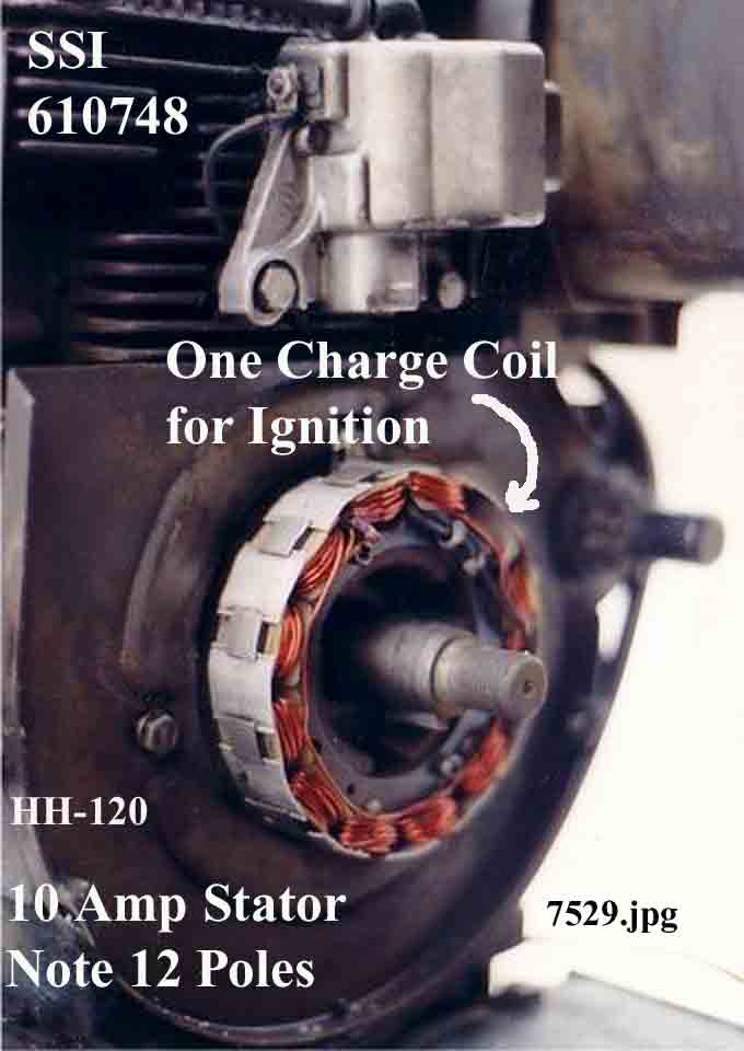
The modification of Tecumseh 610748, 610855
SSI and Onan SSBI3 is not worth the effort because they are too rear or don’t have a printed circuit board in them to
modify and their trigger coils have many more turns that the 610906. The use of a Third Generation Trigger makes more sense.
610906 Modification
The 61906 has a trigger coil in it for triggering
the Silicone Controlled Rectifier, SCR, so I thought why not use that. I tried for several years and could not get it to work
until one day I put a diode in series with the output for some testing and the trigger coil then worked. There are some draw
backs to this approach like the transition from the TDC starting spark to the Advanced spark is very erratic over 100 or so
RPM. This may or may not be a problem, since the engine, once started, ramps up to the idle RPM or higher rather quickly.
Another problem is that the number of turns of wire in the trigger coil is much more that optimum so it puts out an excessively
high trigger voltage. This is overcome by using a very large air gap to raise the transition RPM. The problem here is that
this can compromise the initial starting spark. Not withstanding, this was made to work by crefull testing and adjustment
of the air gap and a couple of hundred engines are running on this approach.

|
| Figure 1-19 |
Figure 1-19, 610906Bot7.jpg shows the bottom
side of a 610906 with some of the potting removed and the printed circuit board exposed. A printed circuit board is made of
a phenolic board ( white here) with a layer of copper on it that has been etched to leave the copper traces that make up the
wires of the device. A green coating is applied to assist in making the solder connections. Modifications to the circuit are
made using cuts and jumpers. A cut in the copper trace is like cutting a wire and a jumper is adding a wire. In the modification
here, all we need is the trigger coil from a failed SSI and the rest of the electronics in the SSI are disconnected and abandoned
in place. Figure 1-19 shows the back of a Tecumseh 610906 SSI with some of the epoxy potting removed. The modifications include
making one cut and adding jumper.

|
| Figure 1-20 |
The first thing to do is to cut off the wire
to spark plug. Next we need to excavate the epoxy potting being careful to stay away from the trigger coil. I use a small
Butane Torch to heat the epoxy then carve it off with an old dull screw driver. ( I know this sounds a little crude for the
Spark Doctor, but it works.) It helps to heat the driver as you go. One has to use caution as the chips of epoxy that come
off are hot and best not be allowed to hit exposed skin. One could start in an area near the ground screw. I also use a soldering
iron to remove epoxy near the end.
There are two diodes connected to the terminal
that need to be disconnected. The easiest way to do this is to un-solder the wire from the PC board and push it towards the
terminal. Leave a pig tail of the wire attached to the terminal as it makes it easy for a later connection. The trigger coil
has one red wire and one black wire. If you expose these, you are going too far. I start the excavation away from the Trigger
Coil and find the PC Board, then use the copper traces as reference to remove the epoxy until I have the trace for the red
wire and the trace for the black wire exposed but not the wires them selves. Extreme caution is required to avoid damaging
the trigger coil.

|
| Figure 1-21 |
The black trace of the trigger coil is to be
jumpered to ground. The ground screw is shown for reference and there is a large copper pad around it. Solder a short length
of black wire on the black trace and the other end to ground pad. By grounding one side of the trigger coil, we will need
only one wire between the trigger and the Control Module.
One cut has to be made on the trace connected
to the Red wire as shown in Figure 1-19, 610906Bot7.jpg above. This separates the trigger coil from the original circuit.
Now is a good time to measure the resistance of the trigger coil. Put one probe of an Ohm meter on the red trace and the other
on the black trace. You should get 9 to 11 Ohms for a good 610906 trigger coil. If the coil is open, the SSI is trash. While
the meter is in hand, measure the resistance between the terminal and the PCB trace where it was disconnected to make sure
it is totally disconnected , open. In order for the trigger to work , we need to add a diode, ( 1N400X, where x is 2 thru
7). So using the diode as the jumper, solder the banded end to the red trace and the other end to the pig tail you left at
the terminal.
Now would be a good time to mount the SSI on
the engine and test it. Start with an air gap between the trigger and the tall trigger pin of .020". Use a YELLOW wire from
the terminal on the SSI to Terminal B on the Control Module. Follow the instructions above, just replacing the Third Generation
Trigger with the modified 610906. After the modified SSI tests good, remove the SSI and fill the cavity made from removing
the epoxy with E6000 or a silicon adhesive.
Pay particular attention to the testing, as
the Modified 610906 will have many more turns of wire than the Third Generation Trigger and will need a wider air gap to try
to compensate for it. If you get the air gap too wide, the spark will be delayed at low RPM and might cause hard starting.
If the air gap is too small, the engine might transition to advanced spark while cranking.
Making a Sewing Machine Bobbin
Trigger
Mostly Copied from older material, but updated
for new findings, new test equipment and test opportunities.
About 10 years ago, I had an ignition failure
with a Tecumseh HH120 and wound up using a Chrysler Control Module and conventional ignition coil. My wife wound a bobbin
on her sewing machine for the trigger coil and it seemed to work, however, later the modified 610906 worked much better. In
this article, I am going back and re-doing this development since I have learned a lot and have better test equipment. I made
about two dozen bobbin coils and tested them to see which was best, which didn’t work and why. The criteria for rating
them was:
1. It must put out a spark by flipping the engine
simulator flywheel by hand, a very low RPM. This is most important for easy starting an engine with a DELCO motor / generator.
2. It must put out an adanced spark above 3400
RPM which is as fast as my engine simulator will run. The original bobbin coils would sometimes fail this test and I solved
the problem by adding a diode like that used on the modified 610906. However, this requires more turns of wire.
3. It must transition from a TDC spark to an
advanced spark between 400 and 600 RPM, (Updated 550 to 750). The number of turns of wire and the air gap determine this transition
point.
4. It must be easy to make from available material,
durable and inexpensive.
As an overview, Figure 1-22, Install.jpg is
a bobbin trigger installed on the engine simulator.

|
| Figure 1-22 |
The Bobbin
I did most of the testing using plastic bobbins
because this is what is used in the electronics industry. I also tried a metal bobbin and sometimes it worked and sometimes
it did not. I think that the plastic bobbin better concentrates the changing magnetic field thru the center of the coil which
is important. So we use plastic bobbins. The Class 15 are wider, thus better, than the Class 66.
The Wire
Magnet wire has a thin insulating coating on
it which prevents all the winding from shorting together. I scrape or sand the insulation off the ends to make the solder
connections. The amount of current drawn by the trigger is so low that the wire size is not an issue. The wire size is limited
on the large size by running out of room on the bobbin. It is limited on the small size by the wire being too fine to work
with. I found that 30 AGW with a measured diameter of .010 inches worked the best. Below, Figure 1-23, 400Turns is a sample
of the data I gathered for this wire which was from Radio Shack. The conclusion is that 400 turns and an air gap to the tall
trigger pin of .012 inches produced a spark from just flipping the flywheel by hand to 3400 RPM with a transition from the
TDC spark to the advanced spark at 537 RPM. One can see how the changes in air gap effects the transition RPM.
400 Turns, 30 AGW, .010 Inches in Diameter
Figure 1-23, 400Turns.

|
| Figure 1-24 |
-
|
Air Gap, Inches |
Transition RPM |
|
.008" |
496 |
|
.010 |
500 |
|
.012 |
537 |
|
.024 |
640 |
The 400 Turns required 50 Feet of wire and measured
a resistance of 5.5 Ohms. The handbook indicates that 100 Feet would be 10.3 Ohms which can be used to estimate the wire length.
It would be acceptable to find some used wire in discarded computer or electronic equipment like a computer CRT monitor. Wire
up to .013 inches in diameter should work, but if you over fill the bobbin, you may have to locate the diode on the terminal
strip instead of on the bobbin.
Figure 1-24, WindMach.jpg shows the wire being
wound. Note that the winding motor turns CCW and the wire is wound CW. So if you are winding the wire by hand, holding the
bobbin in your left hand, you would wind the wire on CW. This determines the polarization and is important. Also note that
the winding started on the side of the bobbin closest the motor. This side will go closest to the mounting bracket.
The winding has two ends, the START end and
the FINISH end. The START end will be connected to diode later. After 400 Turns, put a piece of tape to hold the wire and
a narrow thin strip of E6000 adhesive to keep the wire in place while you finish it.
After the adhesive sets, solder the START end
to the BANDED end of the 1N4005 or equivalent diode. Solder the YELLOW 22 gage stranded lead wire to the other end of the
diode. See Figure 1-25 , Option2B.jpg and Figure 1- 26, Trigger.jpg.

|
| Figure 1-25 |

|
| Figure 1-26 |
Solder the BLACK stranded led wire to the FINISH
end for the ground connection. Bring the YELLOW and BLACK wires around the bobbin in opposite directions and braid them tightly.
Make sure the solder connections don’t touch. When you finished testing, put a coat of E6000 over the windings to fix
and protect them.
The Bolt and Magnet
A soft iron 1/4 - 20, NC bolt, 1 1/4 inches
long is used for the pole piece. Stainless steel or brass won’t work since they are non-magnetic. A 1/4" diameter rare
earth magnet is mounted on the head of the bolt with JB Weld epoxy. Use a compass to make sure the right pole of the magnet
faces the trigger pin, see Figure 1- 26, Trigger.jpg. Be careful to not get the compass any closer to the magnet than necessary
since the magnet can ruin the compass.
Mount the bobbin on the bolt using a nut or
E6000 adhesive after testing, making sure that the side of the bobbin where you started winding faces away from the magnet.
The trigger coil is then mounted on a bracket.
The Mounting Bracket
Some care is required in making the mounting
bracket because the center of the bobbin trigger magnet needs to be centered with the tall trigger pin when the piston is
at TDC,( the key way in the crank shaft is straight up).Use steel because of it’s magnetic properties. I found a length
1 1/4" X 1 1/4" folded steel at Lowes. Figure 1-27 , Bracket.jpg shows the lay out. Tractor Supply has a similar material.
Years ago I found a Bottom Retainer from a series 426 Overhead ( garage ) Door made a great bracket. On the Onan NB, a different
bracket would have to be provided for the Trigger Coil.

|
| Figure 1-27 |
The Trigger Pins
I assume that the interest here is in Tecumseh
engines which already have the trigger pins installed. If this is not the case, trigger pins are available as a kit, Tecumseh
P/N730201.
Testing
Before actually running the engine, the timing
must be checked with a timing light. Figure 1-28, TDCAdv.jpg shows the timing as revealed by an inductive timing light. The
left image shows that the spark occurred just as the tall trigger pin was leaving the trigger at low or cranking RPM. The
image on the right, a higher or running RPM, shows the short, orange trigger pin just leaving the trigger as the spark occurred.
( Actually OEM ignitions show the trigger pin just to the left of the or before the trigger pin, which we should follow. )
There is difference of about 4 Degrees and is the result of a difference in the polarization of the trigger as explained below.

|
| Figure 1-28 |
We need to check the timing at three RPMs.
1. Cranking RPM with compression - definitely
a TDC spark
2. Cranking RPM with no compression,( no spark
plug installed).
3. Running RPM.- definitely an Advanced spark.
( Run a cold engine for 30 seconds or less with the blower housing removed.)
If one needs to increase the RPM of the
transition form TDC to Advanced, increase the air gap by .005 inches. If the engine is hard to start, decrease the air gap
by .005 inches. This lowers the RPM where the ignition first puts out a spark.
Polarization
If the trigger pins are as shown in Figure 1-27,
TDCAdv.jpg the polarization is reversed. If the trigger pins are to the left of the trigger coil instead of the right, the
polarity is as OEM. The trigger coil will output either a negative going pulse followed by a positive going pulse or a positive
going pulse followed by a negative going pulse depending on the direction the wire is wound, the placement of the bobbin on
the bolt or the direction of the poles on the magnet. Reversal of any one of these will reverse the polarity and induce a
4 degree spark advance in the timing. In this case, two wrongs do make a right and the easiest change is to flip the bobbin
on the bolt if you haven’t glued it in place yet.
Conclusion
You can replace the Bobbin Trigger with the
Third Generation Trigger and follow the instructions above.
List of Material for Bobbin Trigger
Bobbins, Plastic
: Micheals, Sewing Basket, or Wife’s sewing basket.
Singer class15, Brother / Kenmore 2518P
Magnet Wire, 30 Gage:
Radio Shack, Three pack, 278-1345, $7 or www.All
Electronics.com (800-826-5432), MW-30-4, 1/4 Lb $8.43
Yellow Lead Wire:
All Electronics, 22YL-25, $2.10 ( For black use a magic marker ) or Radio Shack has 22 gage stranded wire but not yello
Magnets: All
Electronics, MAG-76, 1/4" Dia x .2" , $1. or www.wondermagnet.com .0065, NdFeB Disc 1/4 Dia. X 1/8, $.20 + S&H
Terminal Strip:
Radio Shack, 274-688, four for $1.50
Diode: Radio
Shack, 1N4005, $1 for two, or All Electronics, 1N4005 8 for $1
E6000 Adhesive:
Michaels, $4
Bracket: Steel
WorkS (1305), PlateStl-Angle, 1 1/4" X 1 1/4" - 3FT ( 14GA), Lowes or Tractor Supply
Bolt: 1/4 NC,
1 1/4 Long and nuts
|